
01 · Scope
R744 Gas Cooler Selection Software
The BITZER Gascooler Tool is online selection software for rating BITZER shell-and-tube heat exchangers for R744 (CO₂). One defined operating point is evaluated from the R744 pressure and temperature, the shell-side heat transfer fluid conditions, flow or duty, the fouling resistances and the catalogue geometry. The result contains the thermal, hydraulic and mechanical data required for equipment review.
Capacity Mode – Sizing and Selection
Searches the available catalogue geometry for alternatives that cover a required heat-rejection duty at the stated operating conditions.
Type Rating – Performance Calculation
Calculates one selected geometry and baffle configuration with temperatures, capacity, pressure drops, velocities and technical data.
Serial – 2 gas coolers
Represents the transcritical two-stage arrangement: hot stage GK2, calculated intermediate state, cold stage GK1.
The tool covers a fixed design range of 30–2000 kW. Whether a suitable configuration exists within that range follows from the operating conditions, the available catalogue geometry and the applicable limits. The range describes the scope of the tool workflow; it is neither a capacity guarantee for an individual geometry nor a substitute for current product documentation.
Further information: BITZER DP-400-1 product sheet.
A result is a selection or type-rating result for one operating point. Controls, safety devices, piping, storage, approval, materials and the complete refrigeration or heat-pump design remain separate engineering tasks.
02 · Functions
Device functions and applications
The product is a shell-and-tube heat exchanger with R744 on the tube side and the heat transfer fluid on the shell side. The R744 state on the high-pressure side determines the device function. The use of the transferred heat determines the application. Function and application are independent of each other.
| Device function | R744 state on the high-pressure side | Covered by the tool |
|---|---|---|
| Gas cooler | At or above the critical pressure. Single-phase cooling without condensation; no condensing temperature exists. | Yes, transcritical calculation path. |
| Condenser | Below the critical pressure. Desuperheating, condensation and, where specified, subcooling to a liquid outlet. | Yes, subcritical calculation path. |
| Desuperheater | Below the critical pressure, superheat removal only, without condensation. | No. Subcritical vapour-only operation is rejected; the subcritical path requires a liquid outlet. |
Applications
Heat rejection and heat recovery are applications of these functions, not additional functions. In heat rejection the transferred heat leaves the system through a cooling-water circuit or a downstream air-cooled stage. In heat recovery part of the same heat flow supplies a useful circuit. DP-400-1 assigns heat recovery to transcritical operation, that is to gas-cooler operation.
In transcritical operation the high-temperature part of the heat rejection can be separated into its own stage; the Serial – 2 gas coolers mode calculates that arrangement with a hot and a cold stage. In subcritical operation the desuperheating section carries the highest temperature level, but a vapour-only desuperheater without condensation lies outside the calculation domain.
- Commercial refrigeration, cold stores and distribution centres.
- Industrial and process cooling with a defined heat transfer fluid circuit.
- Heat pumps and hot-water production with a useful heat sink.
- Marine and other installations that require a specific approval and connection configuration.
03 · Thermodynamics
R744 on the high-pressure side
R744 has a critical point at approximately 31.1 °C and 73.8 bar(a). The CO₂ inlet pressure is classified against the critical pressure implemented as 73.773 bar(a): below that value the subcritical calculation path applies, at or above it the transcritical path. The threshold selects the calculation path and the designation marker; it does not describe the remaining cycle.
| Path | Thermodynamic state | Data to specify and review |
|---|---|---|
| Transcritical, gas cooler | R744 is at or above the critical pressure and cools as a single-phase fluid. No high-side condensing temperature exists, and the local temperature difference changes along the heat exchanger. | CO₂ inlet pressure and temperature, outlet target, shell-side inlet and outlet, heat rejection, minimum approach and both pressure drops. |
| Subcritical, condenser | R744 is below the critical pressure. Heat rejection comprises desuperheating, condensation and, where specified, subcooling. The saturation temperature belongs to the selected pressure. | CO₂ pressure and saturation relationship, outlet condition below the saturation limit, capacity and both pressure drops. |
In thermodynamic cycle representations, transcritical heat rejection is approximated as an isobaric, non-isothermal process. In the real heat exchanger a finite tube-side pressure drop occurs and is calculated by the tool. The selected high-side pressure changes the R744 enthalpy and temperature profile, so pressure and outlet temperature belong together. A condensing temperature is not a substitute for a transcritical outlet condition, because no saturation state exists above the critical pressure.
For the current subcritical calculation path the specified R744 outlet condition has to lie at least 0.1 K below the saturation boundary, so that a liquid outlet is defined. This is a calculation-model requirement, not a general recommendation for system subcooling.
04 · Heat recovery
Heat recovery as an application of gas-cooler operation
Heat recovery is not a separate calculation path and not a separate device function. The shell side transfers part of the R744 heat rejection to a useful heat transfer fluid circuit, while the device continues to operate as a gas cooler. Typical sinks are heating-water preheating, process-water heating or another useful thermal load. A result states what the selected geometry transfers at one operating point; the share of that heat the plant can use is not part of the calculation.
R744 properties relevant to heat recovery
In transcritical operation the refrigerant enters at high temperature and cools continuously, and no single condensing temperature fixes the driving temperature difference. The local temperature difference therefore changes along the heat exchanger, which couples CO₂ inlet pressure, CO₂ inlet temperature, gas-cooler outlet temperature and the shell-side temperatures. A water outlet temperature reached at one pressure changes when pressure, mass flow or refrigerant inlet condition change.
Water inlet and outlet temperatures
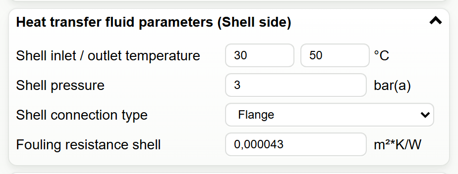
The water inlet temperature is the starting point of the recovery calculation and represents the real circuit entering the shell side, for example cold make-up water, a storage-tank return, a process return or a secondary heating loop. Depending on the selected type-rating mode, the water outlet temperature is either an input or a calculated result. It is limited by the available flow, the heat capacity of the circuit, the local temperature difference, fouling, pressure drop and any water-quality or material restriction. For glycol mixtures the concentration changes density, heat capacity, viscosity and freezing behaviour, so the actual medium and its concentration are part of the operating point.
Countercurrent flow, temperature approach and pinch
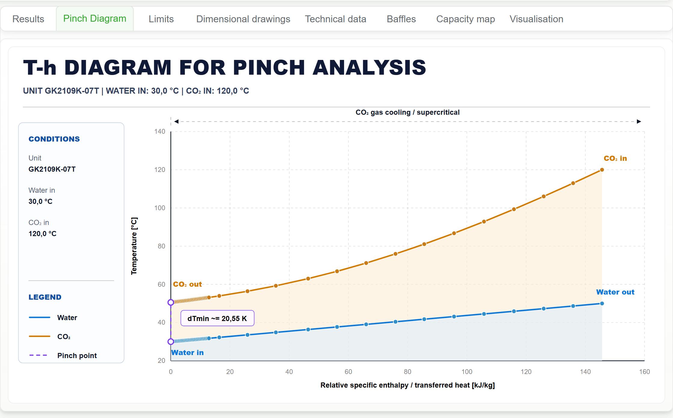
In the countercurrent arrangement the cold water meets the colder R744 outlet end and the warmer water meets the hotter R744 inlet end. This distributes the driving temperature difference over more of the heat-transfer surface and permits a smaller local approach than parallel flow. The pinch is the smallest local temperature difference between the two streams and marks the minimum local driving force, which makes it one of the primary thermal checks for a recovery target. Capacity, R744 outlet condition, shell-side flow, both pressure drops and both velocities belong to the same assessment.
Influence of high-side pressure
High-side pressure acts through the R744 property path. A changed pressure changes the enthalpy difference between inlet and outlet as well as the shape of the refrigerant temperature profile, and therefore the available heat per unit mass and the local pinch distribution. A result is a coupled pressure–temperature operating point, not a fixed water outlet temperature. Where the plant controls the gas-cooler pressure, the recovery calculation applies to the relevant controlled pressure range only.
Integration into the plant
Partial recovery and a high recovered-heat share are different plant arrangements. In partial recovery only a defined part of the high-side heat flow reaches the useful circuit and the remainder is rejected elsewhere. Where the selected heat exchanger carries a high share of the rejection duty, the downstream circuit has to accept that duty across the full operating envelope. The tool rates the exchanger at one point; storage stratification, mixing valves, bypasses, demand variation, auxiliary heat rejection and safety functions belong to the plant design.
After a recovery calculation the relevant checks are capacity, R744 outlet condition, shell-side outlet temperature, pinch, both pressure drops and both flow velocities, compared with the pump curve, the pipework, the control setpoints and the required water temperature. A completed calculation covers the specified operating point only; seasonal and transient plant conditions are not included.
05 · Construction
Shell-and-tube design of the GK series
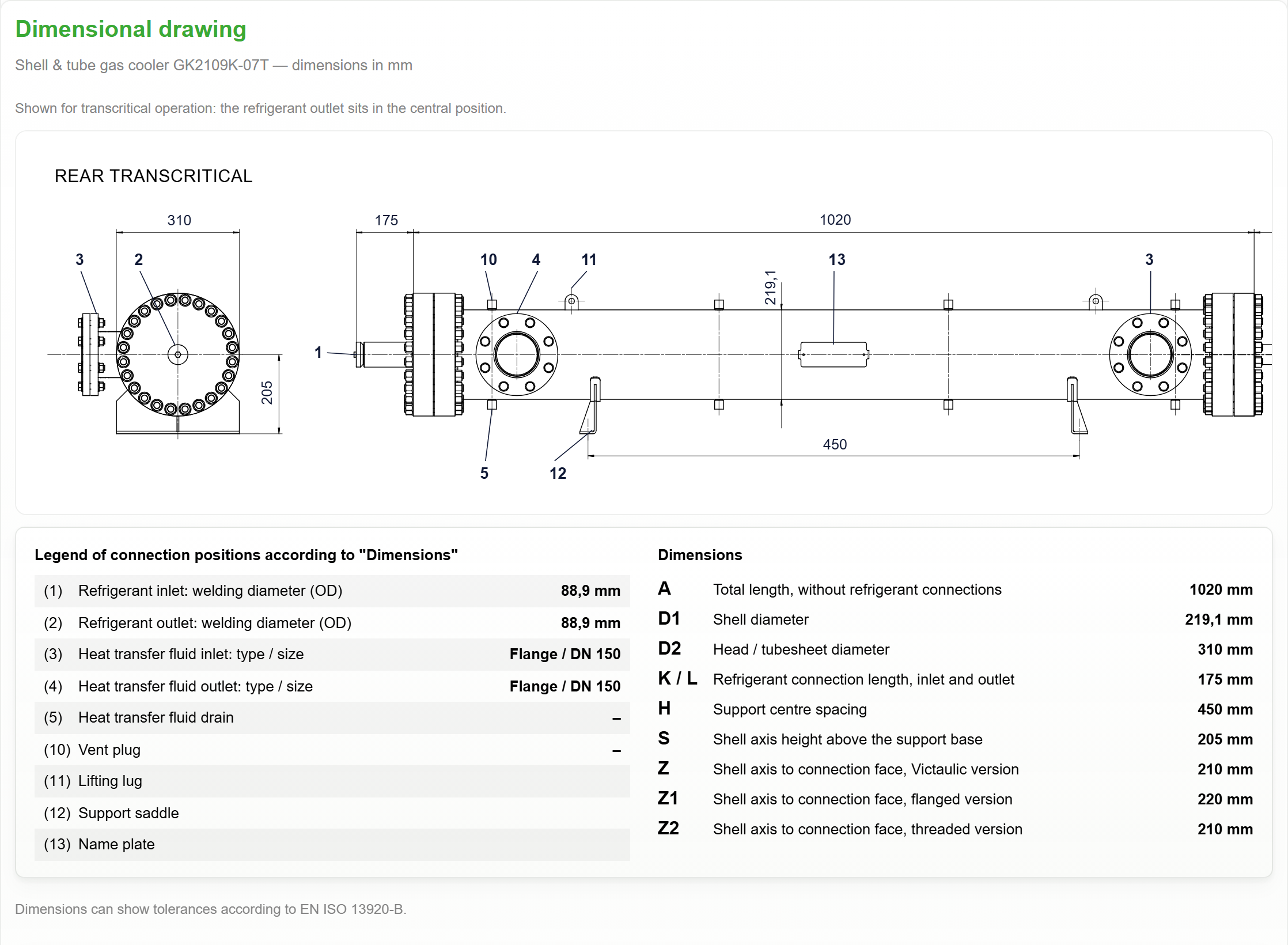
R744 is the primary medium on the tube side, the heat transfer fluid is the secondary medium on the shell side. The tube side carries the R744 high-pressure duty, and the countercurrent arrangement supports a close temperature approach. Tube bundle geometry and baffles link the thermal, hydraulic and mechanical requirements.
Thermal design
Tube-side R744 enthalpy change, shell-side heat capacity rate, heat-transfer area, outlet temperatures and local approach determine the transferred duty.
Hydraulic design
Mass flow, fluid properties, tube passages, shell crossflow, baffles, nozzles and fouling resistance determine pressure drop and velocity.
Mechanical design
Shell diameter, tube length, tube count, baffle arrangement, connections, materials, dimensions, volumes and approval have to fit the installation.
A geometry change is never purely thermal. Tube length changes heat-transfer area, flow path and installed length; tube count changes the parallel flow paths, the tube-side velocity and the tube-side pressure drop; shell diameter changes the shell cross-section, velocity, volume and the available connections; baffles guide the shell-side flow, support the tube bundle and affect crossflow, bypass paths, local velocity and shell-side pressure drop. The current public BITZER GK product sheet describes seven shell diameters, fourteen standard lengths plus on-demand lengths and a range of secondary-side baffle arrangements. Not every combination is available for every operating point, and the tool offers the geometry-compatible options only, so that connections and baffle configuration remain traceable to the catalogue item.
06 · Design trade-offs
Thermal and hydraulic trade-offs
Selection balances heat transfer, pressure drop, velocity, dimensions and operating margin. Sufficient capacity alone does not make a result suitable for a plant. A first energy-balance check is:
The secondary side is screened with:
The overall heat-transfer coefficient (U-value) combines the tube-side and shell-side convective resistances, the wall resistance and the fouling resistances. The solver works with local properties and temperature profiles, so a constant LMTD/U estimate remains a screening check and does not replace the calculation.
| Design lever | Typical effect | Review with the result |
|---|---|---|
| R744 pressure and inlet temperature | Change the refrigerant property path, the available enthalpy change and the local temperature profile. | Gas-cooler outlet, capacity, pinch and operating-mode designation. |
| Heat transfer fluid flow and temperatures | Change the heat capacity rate, the outlet temperature and the shell-side velocity. | Outlet target, duty, shell-side pressure drop and temperature limits. |
| Tube length and tube count | Change heat-transfer area, flow paths, velocity and tube-side pressure drop. | Capacity reserve, CO₂ pressure drop, velocity and overall dimensions. |
| Shell diameter and baffles | Change shell crossflow, bypass behaviour, bundle support and shell-side pressure drop. | Shell and nozzle velocity, pressure drop, baffle configuration and available connections. |
| Fouling resistance and fluid | Fouling resistance adds thermal resistance and reduces the effective U-value. Heat transfer fluid properties influence heat capacity, viscosity, thermal conductivity, heat transfer and hydraulic behaviour. | Project values for the actual water, ethylene glycol or propylene glycol circuit. |
The two pressure drops are assessed separately: the tube-side pressure drop acts on the R744 operating point and outlet pressure, the shell-side pressure drop on the secondary circuit and the calculated shell-side outlet pressure. A clean-side result and a fouled design case are not comparable without stating the difference.
07 · Modes
Operating modes
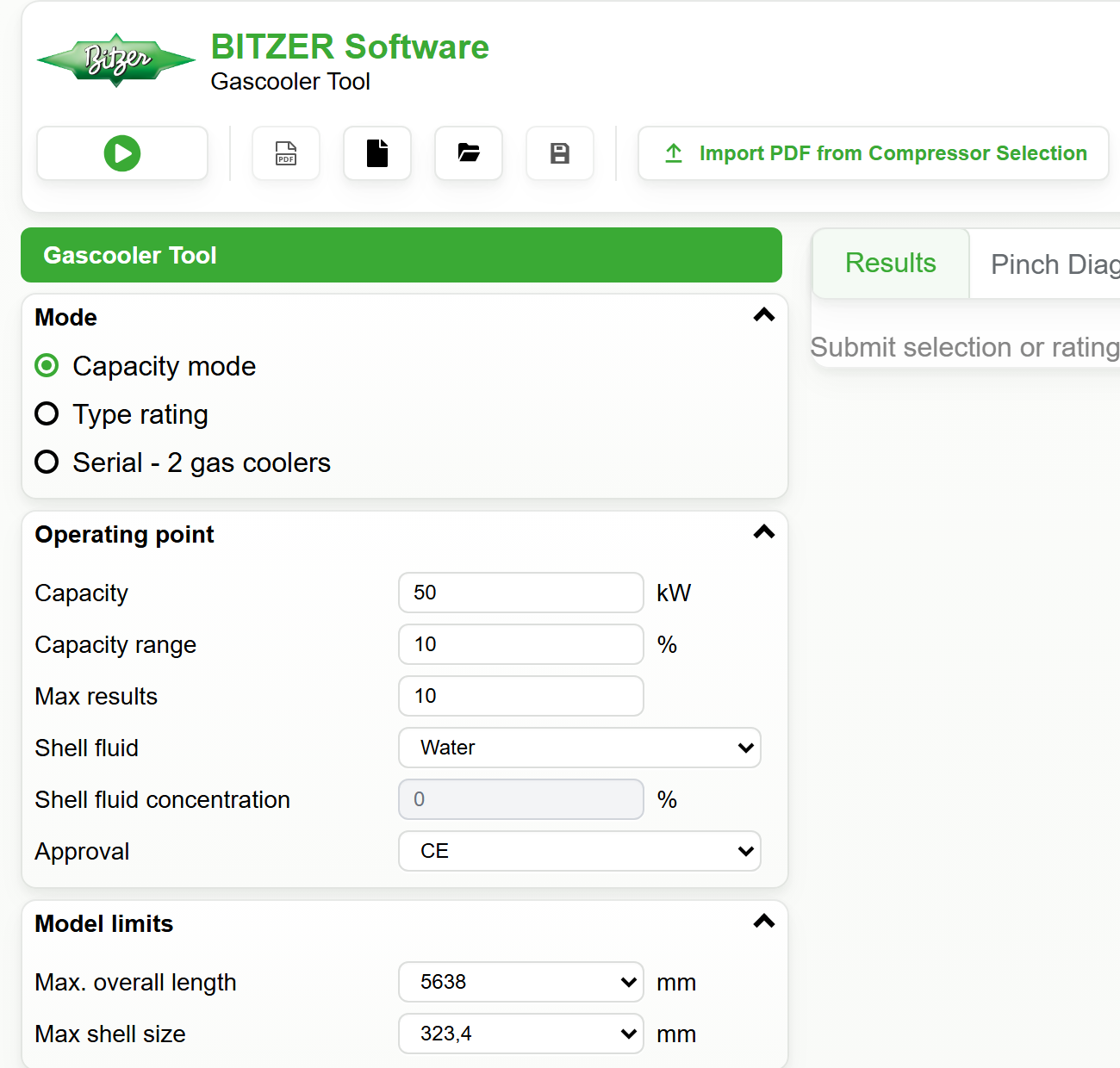
The Mode selector determines the form and the result workflow, that is the engineering question the tool answers. It does not determine the transcritical or subcritical interpretation, which follows from the R744 inlet pressure.
| Mode in the tool | Purpose | Main result |
|---|---|---|
| Capacity mode | Catalogue search for configurations that cover a required duty. | Ranked alternatives with capacity, pressure drops, dimensions, flows, connections and warnings. |
| Type rating | Rating of one model or geometry at a defined operating point. | One calculated candidate with pinch, limits, technical data and visualisation where available. |
| Serial – 2 gas coolers | Rating of a two-stage transcritical arrangement with a hot GK2 and a cold GK1 stage. | Both stage results and the calculated intermediate state. |
Type-rating calculation modes
| Form option | Specified | Determined by the solver |
|---|---|---|
| 1) Shell in + shell volume flow | Shell inlet temperature and shell volume flow. | Shell outlet temperature and heat-transfer result. |
| 2) Shell in + shell out | Shell inlet and shell outlet temperatures. | Shell volume flow required for the thermal duty. |
| 3) Capacity + shell in | Required capacity and shell inlet temperature. | Shell-side state that meets the capacity target. |
08 · Inputs
Inputs and unit handling
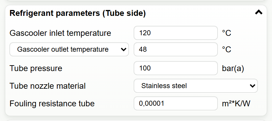
The entered values describe the real operating point. The tool derives only the values defined by the selected mode, the fluid model or the pressure-dependent designation; an entered value is not replaced.
| Input group | Entered by the user | Calculated or selected by the tool |
|---|---|---|
| R744 / tube side | Inlet temperature and pressure, outlet target or CO₂ mass-flow target, tube material, fouling resistance and type-rating connection sizes. | R744 state values, heat-transfer result, tube-side pressure drop and pressure-dependent T/B designation. |
| Heat transfer fluid / shell side | Water, ethylene glycol or propylene glycol; concentration, inlet pressure, temperatures, flow or capacity according to the mode, connection type and fouling resistance. | Fluid properties, shell-side outlet or flow where the mode determines it, shell-side pressure drop and below-atmospheric warning where applicable. |
| Selection target | Required capacity, capacity range, maximum result count, approval and maximum length or shell size. | Candidate filtering, ranking and result diagnostics. |
| Type geometry | Shell diameter, tube length, tube-count code, model or geometry code and baffle configuration. | Geometry-compatible connection options, dimensions, volumes and technical data. |
| Serial arrangement | Stage capacities, shell fluids, temperatures, pressures and geometry limits for the hot GK2 and the cold GK1 stage. | Intermediate CO₂ state and stage results. |
Displayed units and limits
The top-bar controls switch mass flow between kg/h and kg/s, shell flow between m³/h and kg/s, and pressure between bar(a) and kPa(a). Temperatures remain in °C. Unit switching changes the presentation only; the physical operating point is normalised before calculation.
The input checks accept a CO₂ inlet pressure of 20 to 140 bar(a). The shell-side heat transfer fluid inlet pressure has to lie between 1.3 and 16 bar(a). If the calculated shell-side outlet pressure falls below 1.0 bar(a), the tool issues a below-atmospheric warning. Fluid- and pressure-dependent temperature limits remain visible in the form.
In subcritical cases the saturation relationship checks the R744 outlet condition and yields the applicable condenser boundary. An “optimum high pressure” taken from a transcritical compressor selection is not a subcritical condensing pressure.
09 · Workflow
How to Use the R744 Gas Cooler Calculator
The BITZER Gascooler Tool is an online engineering selection, sizing and rating application with three paths. The path follows from the engineering question: search for a suitable configuration, rate one selected type, or evaluate two gas coolers in series.
Path 1: Capacity Mode – Sizing and Selection
The required capacity and the R744 operating point are specified. The tool searches the compatible catalogue geometries, calculates the candidates and compares them by thermal, hydraulic and geometric criteria. A candidate can then be transferred to Type rating.
Path 2: Type Rating – Performance Calculation
One geometry is calculated at the defined operating point in one of the three calculation modes described under 07 · Modes. In every mode the tool also checks the R744 state, the temperature approach, both pressure drops, the velocities, the limits and the available connections.
Path 3: Serial – 2 gas coolers
This path applies to a transcritical two-stage arrangement with two gas coolers in series. The tool calculates the hot and the cold stage with the coupled intermediate state. Plant balance, control and safety design remain separate checks.
Common steps
- Units. Mass-flow, shell-flow and pressure units that match the project documentation.
- Mode. Capacity mode, Type rating or Serial – 2 gas coolers, according to the engineering question.
- Operating point. R744 pressure and temperature, and the medium, concentration, temperatures, pressure and flow of the heat transfer fluid.
- Geometry and connections. Model, tube length, tube-count code, baffles and the connection sizes available in Technical data, matched to the plant.
- Calculation and review. Capacity, temperatures, temperature approach, pressure drops, velocities, limits and technical data together.
- Project file. Load, save or export; documentation of the calculated operating point as a PDF.
Importing a BITZER compressor-selection PDF
Import PDF from Compressor Selection transfers an R744 operating point from a BITZER compressor or system selection into the main form. All 16 operating-software PDF locales and SI/IP units are recognised and normalised. Imported values are reviewed before calculating; a PDF without a selectable text layer has to be exported again from BITZER Software.
10 · Configuration
Tool designation and product configuration
Connections come from the geometry-compatible options offered by the tool. The Technical data tab shows the available shell-side and CO₂ connection sizes, so that the selected heat exchanger matches the plant piping.
| Connection | What you select | How to use it |
|---|---|---|
| Heat transfer fluid, shell side | Connection type and shell connection outside diameter; possible positions are shown in Technical data and the dimensional drawing. | Has to match the secondary circuit and the selected Flange, Victaulic or Threaded configuration. |
| CO₂ inlet, tube side | Tube inlet connection outside diameter and material option where shown. | Has to match the high-pressure R744 inlet line; verified against the dimensional drawing. |
| CO₂ outlet, tube side | Tube outlet connection outside diameter and material option where shown. | Has to match the outlet line; assessed together with tube-side pressure drop and velocity. |
| Technical data | Available catalogue connections, positions, dimensions, volumes and approval information. | Basis for installation coordination. An unlisted plant size is not a substitute for an unavailable catalogue size. |
Approvals
Two approvals are available today. CE is the standard version; the Technical data tab reports its PED category. Marine (DNV, LR, ABS, RINA, BV) is the version accepted by the classification societies for shipboard and offshore installations.
The selection is more than a document: it decides which connection family the catalogue offers, so the same geometry can carry larger nozzles under Marine than under CE, and the dimensional drawing follows it with the longer marine head sections. Plan installation length and plant piping with the approval that will actually be ordered.
Reading the tool designation
The tool adds designation elements that keep the calculated pressure regime and the selected configuration traceable in the result. These software designation elements must not automatically be interpreted as the complete official BITZER ordering nomenclature. In a designation such as GK2742K-07T-1R, GK identifies the product family, 2742K the catalogue geometry, 07 the tube-fill/type variant, T or B the software marker for the pressure-dependent operating mode and -1R the selected baffle arrangement where included.
Automatic regime identification and high-temperature requirement
The tool converts the displayed CO₂ pressure to bar(a) before classification. Below 73.773 bar(a) it uses the subcritical path and the B designation; at or above that threshold it uses the transcritical path and the T designation. The gas-cooler or condenser interpretation follows this classification.
If the heat transfer fluid outlet temperature exceeds 65 °C, a high-temperature version is required. The pressure-based T/B operating-mode marker is independent of this requirement.
11 · Review
Results, diagrams and exports
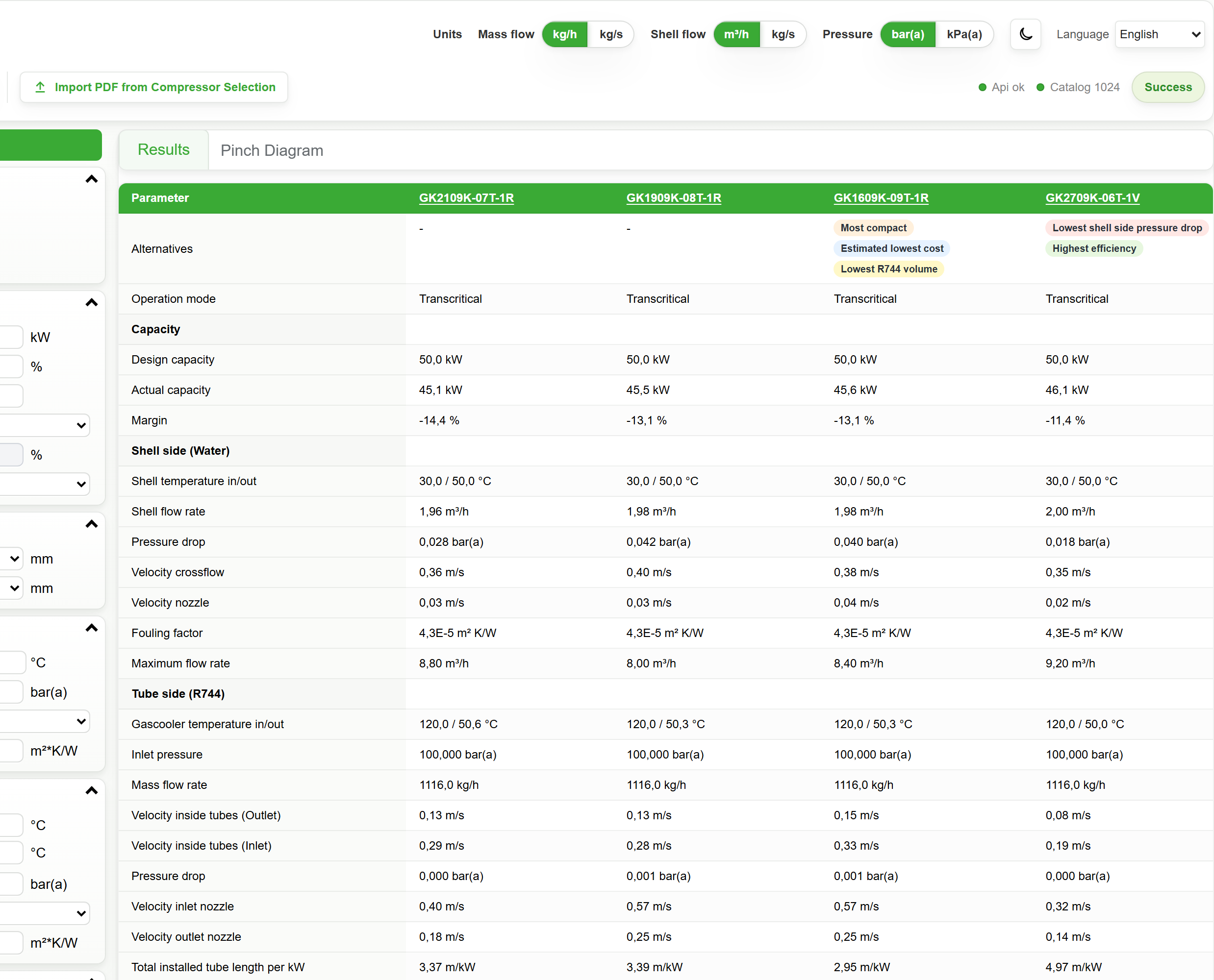
A candidate is assessed as a thermal, hydraulic and mechanical package.
| Result area | Information shown | Relevance |
|---|---|---|
| Results | Operating mode, design and actual capacity, reserve, shell-side temperatures and flow, R744 temperatures and pressure, mass flow, pressure drops, velocities, dimensions, connections and volumes. | Confirms the duty and the assumptions behind the operating point. |
| Pinch diagram | R744 and heat transfer fluid temperature profiles, minimum approach, flow direction and cell trace where available. | Shows the local thermal bottleneck, in particular for heat recovery. |
| Capacity map | Calculated operating points and the available range where the selected result provides them. | Shows the behaviour of the geometry around the current point. |
| Limits | Current values against the applicable input and calculation ranges. | Makes the boundary conditions visible before a result is used. |
| Technical tabs | Dimensional drawings, technical data, baffle influence and interactive visualisation. | Supports configuration review and installation coordination. |
Warnings and traceability information are part of the result. A warning can indicate a hydraulic, thermal, connection or operating-range problem even when the requested capacity is reached.
12 · Engineering use
Notes for project review
- Terminology: gas-cooler terminology applies to the transcritical path; condenser, saturation and subcooling terminology applies to the subcritical path.
- High-side pressure: a transcritical result applies to the selected pressure and inlet temperature and is not a general capacity curve. Optimum system high-pressure control is a separate task.
- Subcritical outlet: the specified R744 outlet condition has to lie at least 0.1 K below the saturation boundary, as a calculation-model requirement.
- Heat transfer fluid: water, ethylene glycol or propylene glycol with the actual concentration; medium, concentration, temperature and pressure determine the fluid properties, the flow, the heat transfer and the pressure drop.
- Pressure: shell-side and tube-side pressure drops are assessed separately, including the calculated shell-side outlet pressure.
- Fouling: project fouling resistances apply on both sides; a clean-side comparison is not an operating design case.
- Geometry: tube length, tube count, shell diameter, baffles and connections are coupled and come from the available catalogue options.
- Approval and documents: the released configuration is verified against current BITZER product documentation.
- Plant design: pressure-equipment design, controls, safety, piping, materials, standards, storage and heat demand are verified separately.
Reference documents: DP-400-1 – GK water gas coolers and AT-744 – Application Guide for R744. Current product documentation and the calculated result take precedence over a generic example.
13 · FAQ
Frequently asked questions
What is a transcritical R744 gas cooler?
A transcritical R744 gas cooler rejects heat on the high-pressure side above the critical pressure and without condensation. R744 cools continuously, so inlet pressure, inlet temperature and outlet condition belong together.
Why is a gas cooler used instead of a condenser in transcritical operation?
Above the critical pressure no high-side saturation temperature exists that could describe the heat-rejection process. Condenser is the term for the subcritical case with condensation.
Is heat recovery a separate device function?
No. Heat recovery is an application of gas-cooler operation: the same heat exchanger transfers part of the rejected heat to a useful circuit instead of to a cooling-water circuit or an air-cooled stage.
Why is R744 suitable for heat recovery?
In transcritical operation the refrigerant temperature falls continuously, so a countercurrent arrangement can produce a large water temperature lift. The usable benefit depends on water inlet temperature, high-side pressure, R744 outlet condition, both mass flows, heat-transfer area, pinch and plant control.
How does the water inlet temperature influence heat recovery?
A lower water inlet temperature can lower the R744 outlet temperature and increase the usable enthalpy difference. It acts together with shell-side flow, required outlet temperature, high-side pressure, R744 mass flow, heat-transfer area and minimum approach.
What determines the achievable water outlet temperature?
R744 state and mass flow, water inlet and flow, heat-transfer area, heat transfer, flow arrangement, fouling, pressure drop and local temperature approach act together. A high water outlet temperature alone is not evidence of a suitable recovery case.
Why is countercurrent flow beneficial?
The colder water meets the colder R744 end and the warmer water moves towards the hotter R744 inlet, which distributes the driving temperature difference more favourably. Pinch, capacity and pressure drop still require review.
What is the pinch in a gas cooler?
The pinch is the smallest local temperature difference between R744 and the heat transfer fluid along the heat exchanger and marks the thermal bottleneck. Where the R744 temperature changes over a wide range, inlet and outlet temperatures alone are not sufficient to assess it.
How does high-side pressure affect a transcritical gas cooler?
High-side pressure affects density, the enthalpy profile, heat transfer, the achievable R744 outlet condition and the compressor work. The tool calculates the heat exchanger at the specified operating point; optimum system high-pressure control is a separate task.
How does tube length affect the capacity?
Tube length, heat-transfer area and flow path are coupled. More length can support capacity and temperature approach, but changes installed length, volume, connections and pressure drop.
How does tube count affect the R744 pressure drop?
Parallel tube paths change cross-section, velocity and tube-side pressure drop. More tubes are not automatically better, because heat transfer, connections and catalogue geometry act together.
What do baffles do in a shell-and-tube heat exchanger?
Baffles guide the heat transfer fluid through the shell and over the tube bundle and support the bundle. They influence flow distribution, heat transfer, pressure drop and local velocities.
Why does the glycol concentration affect the calculation?
The concentration changes density, heat capacity, viscosity and freezing behaviour, and therefore flow, heat transfer and pressure drop. The actual heat transfer fluid and its concentration are part of the operating point.
Why are pressure drop and heat transfer assessed together?
A higher flow can improve heat transfer but also increases pressure drop and pumping power. A suitable geometry meets capacity, pinch, velocity, connection and pressure-drop requirements at the same time.
Can the tool design the complete heat-recovery system?
No. Plant balance, storage, pumps, controls, safety, piping, heat rejection, standards and site conditions remain part of the complete plant design.